General Electric Flying Tips
(Originally from my flying website from 2005 or so. The original publish date is lost)
Tips I’ve gleaned from sites and experience. These are notes I’ve created for myself so they’ll be a little rough. But you’re welcome to look over my shoulder!
Make My Own Battery Packs
9-27-03
Here’s just a couple notes I made to myself about making my own packs. A big thing: If you buy or build a battery pack, make -2-. That way, you can charge them together by making a Y cable.
look more on google: “HR-4/5AUP” buy
and http://www.magtechinc.net/prices.htm
shrink wrap! http://www.tnrtechnical.com/shrinkwrap.html
make a battery pack
http://www.rccentral.com/guides.asp?ATCL_ID=51
look on google: “how to build a battery pack”
check out http://www.batteryspace.com
http://www.dynamoelectrics.com/Supplies.htm
for cheap batteries?
compare to Radio Shack braid:
http://www.dynamoelectrics.com/Supplies.htm
Copper Braid (narrow)
Flat copper braid 1.9mm (.075″) wide x 0.3mm (0.0120″) thick. Equivalent to 18 gauge wire. Up to 10 amps. Per inch.
Doculam covering material
6-13-03
I haven’t tried it yet but the creators of the WagMax Zagi mentioned that they use it. You can buy it here. From what I gather, here are the pros and cons:
-
Way cheaper than Oracover, Monokote, etc.. Oracover costs $11 for a 26″x76″ roll while a 27″ by 500 ‘ (yes, that’s 500 feet) roll of Doculam is $25. Oracover is 40 times more expensive.
-
Doculam is transparent and paintable
-
It shrinks less than the other major coverings.
-
You have to buy it in $50 packs
from http://www.krc.org/planes/slowmo.htm:
The covering supplied with the combo deal is called Doculam. It’s a clear (after heating), light weight material. It is actually a document laminating material that works well for a model covering. It is about 1.5 mils thick, weighs about 1/3 as much as MonoKote, and has it’s own heat sensitive adhesive. The adhesive activates at about the same temperature as MonoKote (325-350 degree F.). It doesn’t shrink as much as MonoKote, so try to keep the wrinkles out as you install it, rather than trying to shrink them all out later. Tom points out that because it is a light weight material, and is not as strong as MonoKote, it should only be used on a slow flyer. The adhesive worked well, and I found the covering fairly easy to work with. Even though it doesn’t shrink as much as MonoKote, I still managed to warp the structure in different areas. A little re-heating and careful twisting straightened out the problem.
I wanted to add a little color to my wing tips, rudder and elevator to make the model easier to see in flight. Tom’s instructions say that the Doculam can be painted on the outside, but says that painting it on the inside actually works best, and ends up more durable. Doculam’s adhesive is not adversely affected by most fast-drying enamel/epoxy/acrylic paints. I was a little skeptical, but I taped a ten-inch square piece to some cardboard and sprayed it lightly with a transparent red Testors spray enamel (on the adhesive side), and allowed it to dry overnight. I used this piece up to cover the top of the wing tips, both sides of the rudder and both sides of the elevator. It really worked great and ironed on just like the unpainted material.
Comparing Doculam and other covering materials
from http://litke.info/uPlanes/compare.html 6-15-03
| Covering Material | ||||
|---|---|---|---|---|
| Supplier | Type | Wt (g/m^2) | thickness (mil) | Comments |
| IMS | Polimicro-Film | 1.3 | 0.035 | |
| WES-Technik | 0.002mm mylar(x12in) | 2.2 | 0.08 | |
| IMS | 0.012oz condenser paper | 3.7 | ||
| Office Depot | waste can liner | 5.8 | frosy clear | |
| IMS | 0.020oz condenser paper | 6.1 | ||
| WES-Technik | 0.004mm alum mylar (x24in) | 6.8 | 0.16 | good for hot air envelopes |
| WES-Technik | 0.005mm mylar (x24in) | 7.0 | 0.20 | |
| Saran Wrap | colored | 11.9 | ||
| Sig | light silkspan | 12.0 | 17.0 doped | |
| Saran Wrap | Cling+ | 12.1 | ||
| JCI | Jap tissue | 13.4 | 19.0 doped | |
| Reynolds | Plastic wrap | 13.9 | crystal blue | |
| mylar | 17.8 | rescue blanket coghlans | ||
| Tony Avak | 0.013mm alum mylar | 19.0 | 0.50 | good for helium envelopes |
| mylar gift wrap | 19.4 | |||
| Solarfilm | lite | 20.0 | approx | |
| Dow | Saran wrap | 20.2 | ||
| Sig | heavy silkspan | 20.7 | 29.0 doped | |
| Airspan | 22.0 | light colored | ||
| gift wrap | 24.0 | |||
| Mylar gift wrap | 26.3 | irridescent | ||
| Litespan | 28.8 | |||
| colored micafilm | 35.0 | |||
| Doculam | 41.5 | 1.5 | ||
| Solarfilm | 68.0 | |||
| TopFlite | MonoKote | 126.0 | ||
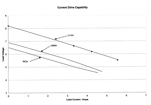
Lithium-Ion Batteries
I haven’t heard of anyone using li-ion on a speed 400 yet. I’ve seen some amazing deals on eBay for computer batteries (i.e. $50 for 50 li-ion laptop batteries) and I’m curious. But I haven’t tried yet. So let’s see…..
A li-ion battery provides 4.2 volts, max of about 3 amps. So to get my Zagi to fly on li-ion, I’ll need 8 cells. 4 parallel packs of 2 cells. That’ll give me 7.2 volts, 12 amps. Or maybe… hmmmm.
from http://www.bktsi.com/skyborn/rcm_july02.htm
LiIon discharge limitations
http://www.ultralifebatteries.com/ rates their LiIon batteries as having a max discharge rate of 2C. Their Li Polymer batteries have a max discharge rate of 1C. I’m thinking that this is going to be too much of a pain to do. I should probably just stick with NiCads.
LiIon defining limitations
from www.ott.doe.gov/pdfs/em-team.pdf on 6-16-03
LiIon has great energy density but poor power density
Defining Terms
Energy density: the amount of energy a battery stores per unit volume at a specified discharge rate; also called volumetric energy density; usually measured in watt-hours per liter.
Power density: the amount of power a battery can deliver per unit volume at a specified state-of-charge; also called volumetric power density; usually measured in watts per liter.
Specific energy: the amount of energy a battery stores per unit mass at a specified discharge rate; also called gravimetric energy density; usually measured in watt-hours per kilogram.
Specific power: the amount of power a battery can deliver per unit mass at a specified state-of-charge; also called gravimetric power density; usually measured in watts per kilogram.
State-of-charge (SOC): the percentage of its total ampere-hour capacity stored in a battery.
USABC: United States Advanced Battery Consortium, a government/industry effort to encourage the development of batteries suitable for electric vehicles.
Wing Loading
from http://www.emfso.org/electric_flight_articles_weight.asp on 6-12-03
Calculated Wing Loading = weight ÷ area = 25 oz/sq ft. (A little higher than desired)
Using “Cubic Wing Loading” better compensates for aircraft size: – – Cubic Wing Loading = 11.3 oz/cu ft. (A little high) Between 9 and 10 oz/cu ft would be better.
(Note: Cubic Wing Loading is an empirical formula that takes into account the affect of aircraft size on wing loading. As a general rule, larger aircraft can handle higher wing loading than smaller aircraft. Cubic wing loading = weight of aircraft in ounces divided by the wing area in square feet to the power of 3/2. [Scientific calculator required!])
Power to weight ratio for a standard Astro 40 power system in this aircraft =
425 – 450W/8Lbs = 53 – 56W/Lb. (Acceptable)
…..
Since this airplane is on the large size for a 40, I also decided a little more power, say 60 to 65W/Lb would be nice
…
so the cell count was increased to 20, with an anticipated power in increased to 470 – 520W depending on the propeller used. [i.e., 25 watts per cell(?)]
from http://www.emfso.org/electric_flight_articles_nicad.asp on 6-12-03
[Everything he says here is right on. I was going to write my own list of tips but he says it just perfectly]
Nicad Care and Handling
by Rod Wooley
Keep your batteries in shape!
There’s no doubt that the one subject guaranteed to raise a heated discussion amongst modelers is nicad care and handling! However, we all need to be expert at battery handling for our radio gear and glow ignitors etc, not to mention it’s useful knowledge with the modern day prevalence of camcorders and portable power tools etc. For the electric-flight enthusiast good battery management is a vital to continued success and happiness, and so this month I will dare to say a few words on the subject.
To cut the verbiage I’ll use point form:
1. Charge new nicads and ones that have not been used for many weeks at a low current of C/10 for 15 or 16 hours. e.g. Charge a 600 mAhr cell at 60 mA. Continuing to charge fully charged cells at C/10 for another day or two will not harm them (except it does slowly reduce their usable lifetime due to cadmium migration into the separator.)
2. Cycle cells or batteries four or five times from new, or after three months or more of storage. This can significantly increase the capacity of a battery up to the rated value. (NB ratings are derived at relatively low discharge currents. Don’t expect the same capacity on heavy loads!) Once cells drop below 80% of rated capacity they should be replaced.
3. Overcharging cells at currents much above C/10 causes overheating and venting and rapidly leads to cell failure.
4. Nicad cells can be stored charged or discharged. It is safer to store them discharged as any nicad can deliver a very high current if shorted. Discharged cells can develop internal shorts but this is unlikely.(I had a pack that was discharged for most of ten years and it still worked fine.) It is not good to leave a load on a nicad battery as it will eventually cause damage once one or more cells are discharged. It is wise not to make a practice of discharging receiver or transmitter batteries by leaving them turned on.
5. Rx and Tx batteries can be managed as follows. Blank off a 15 hour period on a plug in wall timer. (E.g. duct tape) Remove all “on” and “off” plugs except one “off” one at the end of the 15 hour period, and one “on” one 15-20 minutes before. Plug in the C/10 transformer that came with your outfit. A full charge from “new” or “flat” is set up by manually turning on the timer and setting it at the beginning of the 15 hour section. Once charged, the short boost each day will make up for the small self-discharge, and the batteries will be full and ready for flying at any time. (Check voltage “on load” before flying if you do this!) Leaving Rx and Tx permanently connected to the charger is not recommended. (see 1 above)
6. After flying some people estimate the percentage usage of their Rx and Tx packs, add a bit, and charge accordingly. (E.g. 500 mAhr is good for say 100 minutes, 40 minutes of use represents 40% used: charge for 7 to 8 hours) It is also acceptable to provide a full 15 hour charge at C/10, but this is time consuming! Personally I find this too “hit and miss” and slow, and prefer to peak-charge at 500 mA and then put the packs back on the 15 minutes a day “maintenance charge”. ( Use of peak chargers also means that you need to “top up” the charge at C/10 every two or three charges. It is easy to wind in 2 to 3 hours on the timer to compensate for cell imbalance and bring all cells up to a full charge.)
7. Try to avoid discharging a battery below about 1V per cell. (Actually 1.2(N-1) V! This is to avoid cell failure: deep discharges cause a few cells to reverse charge.) A single cell can be taken to a lower voltage and even be shorted (once its voltage is below 1.0 V!), but should not be left in a discharged state for long periods with even a light load.
8. For electric flight applications many modelers have found Sanyo cells -provide unrivaled performance. SCR cells are a fast-charge type of cell and have a low internal resistance and so are ideal for high-current applications. E.g. a 1000 SCR can be charged at 5C or 5 A in 15 minutes, and can be discharged at 50 A (or more!)
9. Small motors, e.g. speed 400, only draw 10 A or less, and to keep weight down cells like the KR600AE are used. These should only be peak charged at just 2.5 C (1.5 A) and used once, followed by a 15 hour C/10 charge (60 mA in this case), or can instead be peak-charged and topped up at C/10 for two or three hours to bring all cells up to full charge.
10. Nicads are damaged by heat and overcharging at higher currents. Use of a good peak charger is recommended, but beware of the “mis-matched cells problem”: usually Sanyo SCR’s are well matched, but for example with camcorder nicads, repeated peak charges gradually leads to a low capacity. This is because some cells are empty before the others, and the effect is accumulative. Eventually the lower efficiency cells will fail. A good long charge at C/10 will often bring such a battery back to full capacity if things haven’t gone too far.
11. Nicads typically maintain a very level voltage over the 10 to 90% portion of the charge discharge cycle. A fully charged cell on charge can be as high as 1.6V. In use, this voltage quickly drops to 1.2 V and then slowly sinks to 1.0 V. After that it drops off quickly during the last 10 % or less of discharge. (On a very heavy discharge the cell voltage can drop immediately as low as 1V as a result of the cell’s internal- resistance, e.g. 4mohm x 50A = 0.2 V).
12. Nicads can be soldered without damage, but clean the terminals well e.g. with a slow Dremel tool using a flexible disc-sander. Avoid shorts due to solder “blobs” around the positive terminal. (Homemade masking tape seals are good). Tin the cell and connection. Use a light smear of flux and multicore solder, and a good powerful iron with a clean flat bit, so the joint is made very quickly before the cell heats up internally. ( Take care! Its easy to damage the nylon seal on the positive terminal!)
13. An accurate digital voltmeter, battery discharger and capacity tester and are very useful equipment for checking batteries. Keep a record of the voltage at the end of a charge and battery capacity. Capacity tests and voltage checks will quickly detect a battery that is starting to fail by detecting shorted cells and cells that are no longer holding a full charge. A good test is to measure capacity once immediately after charging, and then measure capacity again 3 or 4 days after a charge. Any pack that shows a marked drop should be replaced. A drop of 10% in capacity is the most one should consider safe after this time. (Obviously if a pack has not been used much in recent weeks it’s worth cycling the pack 3 or 4 times before checking capacity) A good test of an individual cell is to take it to zero volts and then short it out for 24 hours. Remove the short and see if the cell will re-establish some voltage greater than zero. If it does this it means it is free of any high-impedance internal shorts.
14. On electric models it seems to be best to store the propulsion batteries discharged until just before use, and then to peak-charge them. Land as soon as the pack starts to drop off so you still have control, and then run the battery down until there is not much “umff” left. Thus full charge, full discharge seems to work well and provide maximum capacity, although I am not sure why it is superior. It may be because it helps to avoid the mismatch problem mentioned above, perhaps because empty cells can’t self-discharge at different rates and get out of step!
Rod Woolley (Ottawa RC club)
Selecting the right electric motor, battery, prop, and gear ratio combination
from http://www.emfso.org/electric_flight_articles_wire.asp on 6-12-03
After much pondering, I have concluded that the biggest problem most people have is in selecting the right battery, motor, propeller and gear ratio combination. To do this right, you need at least a tachometer, an ammeter and a bit of common sense. If you don’t want to understand how to use these simple tools, at least find someone who does, and get them to do a quick check on your setup. It will immediately tell you what is happening and how your plane could possibly be improved. If you throw up your hands in dismay and say “I don’t know nuthin’ about that technical mumbo-jumbo!”, you missed the point! You don’t need to be a whiz-kid. You just need to know a couple of simple facts and how to apply them.
The first fact is that the speed at which a propeller will want to fly is approximately its pitch in inches times its RPM in thousands! i.e. MPH = pitch X rpm/lO00. Now you know what use a Tach is! You can work the thing out in your head once you have the RPM! In the air, the prop will unload a little, so add about 10% to its static RPM to get its flying RPM. Now you know why a 12 X 6″ prop turning at 4,000 RPM will not give a sparkling performance to an aerobatic sport plane that has a stall speed of 25 MPH. You also know that a 12 X 8″ folder turning at 6,000 RPM on your 25 MPH sailplane is just eating up batteries and cooking the motor.
The second fact you need to know is that power is amps times volts. At the current levels we use, we can assume that there is about one volt across each nicad cell in the battery pack. Therefore, power = amps x number of cells. This will tell you how much electrical power is being converted in your motor into mechanical energy and heat. Now you know the use of an ammeter! Again, you can do the calculations in your head! In the air, the motor will draw about 20% less current as it unloads, so flying current = 80% of static current. Now you know that if your IOOW can motor is drawing 25 amps on seven cells, you know it is not long for this world! You also know that if your Astro 40 is drawing 10 amps on 16 cells, you need a bigger prop or you might as well use an Astro 05! You must admit, none of the above really strained your brain and you didn’t even have to find batteries for your calculator! When you put the two simple facts together, you can find the right sized prop to match your motor and plane. If you can’t guess roughly how fast your plane will fly, ask someone with experience. You will know if they have experience because they will ask you what the wing area is and how much the plane weighs. If they can’t see your plane, they will also ask you how thick the wings are and what shape the aerofoil is, as well as what kind of performance you want. Then all you need to do is borrow a few props if you don’t have any and check the motor current and the RPM for each until you get the results you want. Then you can go out and buy the right sized prop and confidently join me in the clouds.
Propeller Diameter and RPM
from http://www.eskimo.com/~smallnet/JoeArticles/Propellors.html 6-14-03
The most important variables affecting the thrust a propeller can develop are its diameter and rpm. Thrust increases when either of those go up — in proportion to the square of the rpm, and the FOURTH POWER of the diameter. If you should speed up an engine-driven prop from 10,000 to 14,142 rpm, its thrust output would double. And if you spin a ten-inch prop at the same rpm as a geometrically-similar 5-incher, the thrust developed will be SIXTEEN TIMES as great.
… [large props are more efficient and quieter than small props]…
… [it’s very important to have a very stiff blade]…
Here’s a handy “rule of thumb” concerning propellers. The maximum speed a propeller-driven aircraft can attain is roughly equal to the prop pitch in inches, times its rpm in thousands.
Example: An 8-4 prop at 10,000 rpm can’t pull its model faster than 40 mph. (4 inch pitch times 10K rpm = 40 mph maximum.) The airplane can fly a lot SLOWER — particularly if it’s a high- drag design. But even in a dive, it won’t go faster than this “rule of thumb” limit.
The Best Propeller Tip Speed
from http://www.masterairscrew.com/techbull.asp on 6-14-03
An interesting point in understanding power absorption is that propeller power varies as the cube of the rpm. Consequently, twice the rpm requires 8 times the power.
Tip Speed is measured in feet per second and a formula is provided below to find this measurement.
For model airplane purposes, the best tip speed for efficiency and noise requirements is 600 feet per second. This is due to compressibility losses and the fact that subsonic airfoils do not work well in transonic/sonic speeds with required sound levels.
Feet Per Second (ft/s) = RPM x diameter in inches x .00436
For example, to find the tip speed of a 10×6 on a .40 size engine running at 13,500 RPM, the equation would be 13,500 x 10 x .00436 = 588.6 ft/s.
To find the correct diameter at 600 ft/s, use this formula:
Diameter in inches = 138,000 / RPM
Using a .40 engine running at 13,500 RPM, the equation would read as follows:
138,000/13,500 = 10.22
Rounding down, the correct diameter is 10″
Comparison of different speed 400 motors (especially brushed vs. brushless)
from http://www.emfso.org/electric_flight_articles_motor_comp.asp on 6-12-03
| Ferrite “Can” | Ferrite Car | Cobalt/Neo | Brushless | |
| Cost | Low cost – $10..$30 | Medium cost – $20..$50 | High cost – $125..$600 | Very high cost $400 + |
| Quality | – Low quality – Brass bushings – Carbon brushes on leaf springs – Cheap ferrite magnets – Large armature-magnet gap |
– Medium quality – Bushings or ball bearings – Copper or silver brushes – Brush holders and separate springs – Better ferrite magnets – Some have adjustable timing |
– High quality – Ball bearings – Thicker output shafts – Large brushes (usually silver) – Brush holders and separate springs – Powerful cobalt or neodym magnets – Adjustable timing |
– High quality – Ball bearings – Thick output shafts – No brushes – Powerful cobalt or neodym magnets – Adjustable or self-adjusting timing |
| Weight | Heavy (~2.3lb/HP) | Heavy (~2.3lb/HP) | Light (~1.5lb/HP) | Very light (~0.5 to 1.2lb/HP) |
| Efficiency | – Narrow efficiency curve – Maximum efficiency about 70% – Typically about 60% |
– Narrow efficiency curve – Maximum efficiency about 75% – Typically about 65% |
– Wide efficiency curve – Maximum efficiency about 80% – Typically about 70% |
– Wide efficiency curve – Maximum efficiency about 85% – Typically about 75% |
| Power | – Maximum power at about 50% efficiency – About 140W out for a 7oz motor |
– Maximum power at about 55% efficiency – About 140W out for a 7oz motor |
– Maximum power at about 60% efficiency – About 220W out for a 7oz motor |
– Maximum power at about 65% efficiency – About 280W out for a 7oz motor |
| Advantages | – Cheap! – Readily available – Can often be found surplus – Wide range of sizes – Low cost is great for multi-motor models |
– Fairly inexpensive – Readily available – Brushes replaceable – Some have ball bearings – More efficient than “cans” |
– Brushes replaceable – Ball bearings for long life – More efficient than car motors – Low maintenance – Wide voltage and current range |
– Zero maintenance – Ball bearings for long life – More efficient than brushed motors – Very wide voltage and current range |
| Disadvantages | – Difficult to maintain – Brushes not replaceable – Loses power at high temperatures |
– Difficult to find specifications – Limited selection of sizes |
– Fairly expensive – Harder to get |
– Very expensive – Requires special speed control – Not usually in stores |
| Examples | – Graupner Speed 400, 600, 700 – Great Planes Goldfire and Thrustmaster – Master Airscrew |
– Kyosho Magnetic Mayhem – Trinity Speed Gems (Ruby, etc.) – Leisure Model Electronics |
– Astro Cobalt – Cermark Cobalt – Graupner Ultra Neodym |
– Astro Brushless 020 and 05 – Aveox – MaxCim – Kontronik |
| Effect on Power – Sailplane with 12×8 prop and 7×2000 cells, geared for 4 minute run |
– Graupner #1793 Speed 600 7.2V – 2.65:1 gearbox – 25A input – 123W output |
– Kyosho Magnetic Mayhem – 2.7:1 gearbox -25A input – 128W output |
– Astro #605 Cobalt 05 Sport – 2.5:1 gearbox – 25A input – 146W output |
– Aveox 1406/3Y – 2.4:1 gearbox – 25A input – 159W output |
| – Effect on Run Time – Sailplane with 12×8 prop and 7×2000 cells, geared to give 138W output |
– Graupner #1793 Speed 600 7.2V – 2.2:1 gearbox – 32A input – 138W output – 3:12 run time |
– Kyosho Magnetic Mayhem – 2.3:1 gearbox – 31A input – 138W output – 3:19 run time |
– Astro #605 Cobalt 05 Sport – 2.6:1 gearbox – 23A input – 138W output – 4:24 run time |
– Aveox 1406/3Y – 2.55:1 gearbox – 22A input – 138W output – 4:44 run time |
Graupner #1793 Speed 600 7.2V
Kyosho Magnetic Mayhem
Astro #605 Cobalt 05 Sport
Aveox 1406/3Y
Prop Diameter to Pitch Ratio
from http://www.emfso.org/electric_flight_articles_props.asp on 6-12-03
The diameter to pitch ratio is important. 12×6, 11×8, and 10×10 props absorb about the same amount of horsepower. Trainers and biplanes should use a diameter to pitch ratio 2:1 (i.e.. 12×6). Very draggy planes like a tripe might be better off using 3:1 (i.e.. 14×6). Sport planes can use a 1.5:1 (i.e.. 9×6). Fast planes racing planes might use a 1:1 ratio (i.e.. 10×10).
from http://atlantasolar.com/gasolar/batterycare.html on 6-12-03
Measuring Lead-Acid Battery Condition
Connect a voltmeter and measure the voltage across the battery terminals with the battery at rest (no input, no output) for at least three hours. These readings are best taken in the early morning, at or before sunrise, or in late evening. Take the reading while all loads are off and no charging sources are producing power.
The following table will allow conversion of the voltage readings obtained to an estimate of state of charge. The table is good for batteries at 77·F that have been at rest for 3 hours or more. If the batteries are at a lower temperature you can expect lower voltage readings.
You can see that when your voltage reading is about equal to
the battery “nominal voltage”your battery is about 60% discharged.
Battery State of Charge Voltage Table
| Percent of Full Charge | 12 Volt DC System | 24 Volt DC System | 48 Volts DC System |
| 100% | 12.7 | 25.4 | 50.8 |
| 90% | 12.6 | 25.2 | 50.4 |
| 80% | 12.5 | 25 | 50 |
| 70% | 12.3 | 24.6 | 49.2 |
| 60% | 12.2 | 24.4 | 48.8 |
| 50% | 12.1 | 24.2 | 48.4 |
| 40% | 12.0 | 24 | 48 |
| 30% | 11.8 | 23.6 | 47.2 |
| 20% | 11.7 | 23.4 | 46.8 |
| 10% | 11.6 | 23.2 | 46.4 |
| 0% | <11.6 | <23.2 | <46.4 |
The following chart reflects state of charge vs. specific gravity of the electrolyte in each cell.
A hydrometer is used to determine specific gravity.
| State of Charge | Specific Gravity |
| 100% Charged | 1.265 |
| 75% Charged | 1.239 |
| 50% Charged | 1.200 |
| 25% Charged | 1.170 |
| Fully Discharged | 1.110 |
| These readings are correct at 75°F | |